To start a site plan rendering, a studio requires georeferenced CAD files (DWG/DXF), topographic survey data, boundary and zoning documents, material specifications, landscape intent, and a clear project brief that defines output resolution, camera perspective, and final deliverable format. Without these core inputs – specifically accurate base geometry, grading data, and finish schedules – the studio cannot begin 3D modeling, and delays or revision cycles are nearly inevitable. Understanding exactly what information is needed to start a site plan rendering is the single most important step a developer, architect, or project manager can take before placing an order.
Every day spent waiting on missing files is a day your rendering timeline slips. This guide breaks down every document, file, and decision you need to prepare so your studio can start immediately – and deliver exactly what you envisioned.
Working with a professional 3D site plan rendering company means your project’s success depends as much on what you submit as on the studio’s technical skill. Let’s walk through the complete checklist.
Why the Information You Submit Changes Everything
Many clients assume a rendering studio just needs “the plans.” In reality, the quality, accuracy, and turnaround time of your 3D site plan rendering are directly determined by the completeness of your submission package.
Here’s what happens without a proper brief:
- The studio makes assumptions about materials, finishes, and landscaping
- Revision rounds multiply because the output doesn’t match your vision
- Modeling time – the most expensive phase – increases dramatically
- Delivery timelines stretch by days or weeks
According to industry best practices from studios like ArchiCGI, every element left unspecified in a brief gets decided by the studio, not by you. That creates misalignment from the start.
The solution is straightforward: submit a complete, organized package from day one.
The Complete Checklist: What Information Is Needed to Start a Site Plan Rendering
1. Georeferenced CAD Files (DWG or DXF)
This is the foundation of every 3D site plan rendering. Your CAD files must be:
- In DWG or DXF format (not PDFs or scanned images)
- Accurately georeferenced and drawn to real-world scale
- Layered correctly with descriptive layer names
- Clean of duplicate geometry, overlapping lines, and broken polylines
A PDF is not sufficient on its own. While studios can trace over a PDF, this adds manual modeling time and introduces errors. A clean DWG file allows the team to import directly into 3D software and begin working immediately.
What to include in your CAD submission:
- Full site boundary with property lines
- Building footprints, pad locations, and setbacks
- Roads, driveways, parking lots, and pedestrian paths
- Utility corridors and easements
- Existing and proposed grading contour lines
2. Topographic Survey Data
Topography defines how the land actually sits. Without accurate elevation data, the studio renders a flat site – which looks wrong and misrepresents the project to stakeholders.
Acceptable topographic formats include:
- Civil 3D survey files with contour intervals
- GIS-exported DEM (Digital Elevation Model) data
- LiDAR point cloud files (.LAS or .LAZ)
- Stamped topographic survey in DWG format
Even for relatively flat sites, include benchmark elevations and spot grades at key points such as building entries, drainage swales, and site perimeters.
3. Boundary and Zoning Documents
Your studio needs to understand the legal context of the site. Provide:
- Recorded plat or legal description of the parcel
- Zoning setbacks, easements, and rights-of-way
- Phase boundaries if this is a multi-phase master plan
- North arrow and site orientation
This data ensures the rendering reflects the actual buildable area and does not misrepresent the project during approvals, permitting, or marketing presentations.
4. Architectural and Civil Engineering Drawings
Beyond the base site plan, the studio needs supporting design documents to populate the scene with accurate structures. These typically include:
| Drawing Type | Why It’s Needed |
|---|---|
| Floor Plans (all levels) | Establishes building footprint, entries, and massing |
| Exterior Elevations | Defines facade heights, window positions, and materials |
| Roof Plan | Confirms roof pitch, overhangs, ridgelines, and features |
| Grading and Drainage Plan | Shows how land flows, swales, retaining walls, and berms |
| Landscape Plan | Defines tree species, shrub masses, lawn areas, hardscaping |
| Utility Plan | Shows service infrastructure visible at grade level |
If Revit or SketchUp models already exist, provide them. These dramatically reduce modeling time and improve accuracy compared to 2D drawings alone.
5. Material Specifications and Finish Schedules
Material specifications are the biggest single variable in determining how many revision rounds you will go through. Vague descriptions like “modern exterior” or “natural landscaping” require the studio to guess – and guessing leads to revisions.
What to provide for each material surface:
- Manufacturer name and product line
- Color code or material sample reference
- Texture direction (horizontal, vertical, running bond, etc.)
- Surface finish (matte, polished, weathered, painted)
- Reference photos from manufacturer catalogs or project moodboards
For landscaping, specify:
- Tree species and approximate mature canopy sizes
- Ground cover types (grass, gravel, mulch, pavers)
- Hardscape materials for patios, plazas, and pathways
- Water features, fences, site furniture, and lighting fixtures
Studios that receive detailed finish schedules deliver dramatically fewer revision cycles than those working from vague verbal descriptions.
Project Brief Requirements: The Document That Guides Everything
Even with excellent drawings, studios need a written project brief to align on outcomes. Think of this as the communication layer on top of the technical files.
What Your Project Brief Must Include
Project Identification:
- Project name and address
- Client name and primary contact
- Project type (residential, mixed-use, commercial, master plan, etc.)
- Current design phase (schematic, design development, construction documents)
Output Specifications:
- Final image resolution (minimum 3000 x 2000 px for print; 1920 x 1080 px for digital)
- Aspect ratio requirements
- File format (TIFF, PNG, JPEG, PSD with layers)
- Number of views or rendering angles required
Camera and Perspective Direction:
- Preferred viewpoint (aerial/bird’s-eye, oblique, ground-level, isometric)
- Altitude or camera height for aerial views
- Key elements that must be visible in frame
- Any angles to avoid (neighboring structures, incomplete phases)
Time of Day and Lighting:
- Desired time of day (morning, golden hour, midday, dusk, night)
- Season and foliage state (summer lush, autumn color, winter bare)
- Sky condition (clear blue sky, dramatic clouds, overcast)
- Artificial lighting needs for evening views
Intended Use:
- How will the rendering be used? (investor deck, planning submission, website, billboard, social media, sales brochure)
- Required deadlines and milestone dates
Reference Images and Visual Direction
Reference images are one of the most underutilized tools in a client submission package. They communicate style, mood, and quality expectations far more efficiently than written descriptions.
Types of reference images to include:
- Rendering style references – Examples of 3D site plan renderings you admire, showing the visual quality and style you expect
- Material and finish references – Manufacturer product images or photos from similar completed projects
- Landscaping references – Images of the tree species, planting style, and seasonal condition you want depicted
- Lighting and atmosphere references – Photos or reference renders showing the time of day and mood you are targeting
- Context photos – Current site photographs, street view images, and aerial photos from Google Earth or similar sources
Create a clearly organized folder labeled “Visual References” and include a short note with each image explaining what specifically you are referencing – the material, the light quality, the tree scale, etc.
According to architectural visualization best practices documented by No Triangle Studio, the more of the full design package and visual context you share, the better the studio can match your intent without guessing.
Comparison Table: Submission Quality vs. Project Outcomes
| Submission Quality | Modeling Time | Revision Rounds | Delivery Timeline | Final Quality |
|---|---|---|---|---|
| Complete (CAD + survey + brief + materials) | Minimal | 1-2 rounds | On schedule | Photorealistic |
| Partial (drawings only, no brief) | Moderate | 3-5 rounds | Delayed by 3-7 days | Good but misaligned |
| Minimal (PDF only, verbal description) | High | 5+ rounds | Significant delays | Generic or inaccurate |
| Incomplete (no survey, missing elevations) | Very high | Ongoing revisions | Unpredictable | Unusable for submissions |
Common Mistakes Clients Make Before Sending Files
Even experienced developers and architects make submission errors that delay their projects. Here are the most frequent ones:
Sending PDFs Instead of Native CAD Files
PDF drawings seem convenient, but they require the studio to manually re-trace geometry – a time-consuming process that introduces inaccuracies. Always export native DWG or DXF files from your CAD software.
Omitting Grading and Topographic Data
Sending only the horizontal layout without elevation data produces a flat-looking render that misrepresents the actual site. Even gentle grades of 2-3% dramatically affect how the site reads visually.
Using Vague Material Descriptions
Telling a studio “use warm stone tones and modern glass” is not a material specification. It is an invitation for guesses. Specific manufacturer references and color codes eliminate ambiguity entirely.
Forgetting Context Beyond the Property Line
A 3D site plan rendering typically shows surrounding streets, neighboring buildings, and adjacent landscape. Provide aerial imagery, street view screenshots, and GIS data for at least 100-200 feet beyond the site boundary.
Not Specifying the Final Intended Use
A rendering destined for a 300 dpi printed brochure requires different resolution settings than one intended for a website homepage. State the intended use clearly in your brief.
Submitting Files Without Naming Conventions
Folders labeled “Final v3 REVISED NEW” or files named “untitled-02-copy” slow down every studio workflow. Use clear, descriptive file names and a logical folder structure.
Step-by-Step Guide: How to Prepare and Send Your Files
Follow these steps before contacting your rendering studio:
Step 1: Export CAD Files in Native Format Open your CAD or BIM software and export site plan drawings as DWG or DXF. Confirm the file uses real-world coordinates and is set to the correct scale (1:1).
Step 2: Organize Your Topographic Data Gather your civil engineer’s grading plan, topographic survey, and any GIS or LiDAR data. Confirm all elevations are referenced to a consistent benchmark datum.
Step 3: Compile Architectural Drawings Collect all elevations, floor plans, roof plans, and section cuts. If a Revit or SketchUp model exists, export it and include it as a supplement.
Step 4: Build Your Material Specification Sheet Create a spreadsheet listing every exterior surface, its manufacturer, product name, color code, finish, and a linked reference image. Do the same for all landscaping elements.
Step 5: Gather Context Data Download aerial photography from Google Earth or your county GIS portal. Take or gather street-level photography of the site and surrounding neighborhood.
Step 6: Complete Your Project Brief Fill in all output specifications, camera angle preferences, lighting direction, deadline dates, and intended end use.
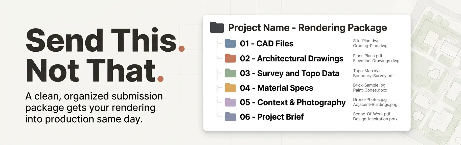
Step 7: Organize into Clearly Labeled Folders Structure your submission like this:
Step 8: Send via File Transfer (Not Email Attachments) Use cloud storage such as Google Drive, Dropbox, WeTransfer, or a dedicated project management portal. Email attachments frequently fail size limits and corrupt compressed CAD files.
Expert Tips for a Smoother Rendering Process
These insights come directly from the workflows of professional architectural visualization studios:
Tip 1: Send More Than You Think Is Necessary Studios can always ignore irrelevant data. What they cannot do is invent missing information without making assumptions. Over-sharing is always better than under-sharing.
Tip 2: Flag Design Intent Clearly If certain elements are still conceptual or subject to change, label them in your brief. This prevents the studio from investing heavy modeling time in areas that may change after your next design review.
Tip 3: Schedule a Brief Call Before Submitting A 15-minute kickoff call with your studio before you send files resolves ambiguities, confirms format preferences, and aligns expectations – saving hours of revision time later.
Tip 4: Agree on Revision Scope Upfront Define what constitutes a revision versus a new deliverable in your contract before work begins. Moving a camera angle is a minor revision. Changing the entire landscaping scheme after the first draft is a scope change.
Tip 5: Request a File Review Before Production Begins Ask the studio to confirm receipt and completeness of your submission before they begin modeling. This gives both parties a chance to catch missing items before time is invested.
To understand the full visual scope of what these deliverables produce, read our detailed overview of what a 3D site plan rendering actually is and how studios transform your documents into photorealistic output.
Special Considerations by Project Type
Different development types have slightly different submission requirements. Here is a quick reference:
Residential Subdivision Site Plans
- Include lot numbering and lot size schedule
- Provide typical house footprints for each lot type if homes are included
- Specify HOA-governed landscape standards and materials
- Include entry monument, signage, and amenity area details
Mixed-Use and Commercial Developments
- Submit separate elevation drawings for each building type
- Clarify retail, office, and residential zone differentiation in the rendering
- Include parking structure levels and podium configurations
- Specify signage and branding elements if required
Master Plan and Large-Scale Residential Communities
- Provide phasing plan with phase boundary polygons
- Identify which phase the rendering focuses on vs. which is shown as future development
- Include amenity area details: clubhouses, pools, recreational facilities
- Provide street section drawings for boulevard and collector road treatments
Multifamily and High-Rise Projects
- Include podium and tower relationship in 3D model or section drawings
- Specify balcony, railing, and cladding systems in detail
- Provide mechanical penthouse and rooftop element drawings
- Clarify whether adjacent development context needs to be modeled accurately
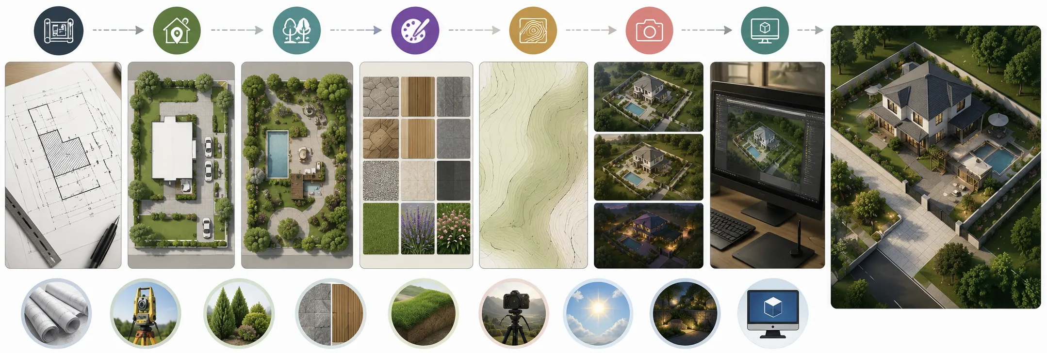
What Happens After You Submit Your Files
Understanding the studio’s production workflow helps you set realistic expectations and communicate effectively during the process.
- File Review and QA – The studio confirms all files are received, reviews for completeness, and flags any missing items before modeling begins
- 3D Base Modeling – Artists build the 3D geometry from your CAD and BIM data, establishing accurate building footprints, massing, and site grading
- Material and Texture Application – Based on your finish schedule, the team applies materials, colors, and textures to every surface
- Landscaping and Context Population – Trees, shrubs, ground cover, site furniture, vehicles, and surrounding context are added to populate the scene realistically
- Lighting and Camera Setup – The rendering team establishes the time of day, sun angle, sky condition, and camera position per your brief
- Draft Render Review – A first-pass draft image is delivered for your feedback
- Revisions and Final Delivery – Based on your review notes, the studio makes approved revisions and delivers final high-resolution files
The quality and completeness of your initial submission directly influences how smoothly each of these stages proceeds. A complete package means steps 1 through 5 happen without interruption. An incomplete package creates holding patterns at nearly every stage.
For an in-depth look at how professional studios approach aerial and oblique viewpoints, Google’s guidance on user-first content and rendering expectations aligns with what top studios consistently deliver: specificity, accuracy, and visual communication that serves the end viewer’s understanding.
FAQ: What Information is Needed to Start a Site Plan Rendering
Q: What is the minimum information needed to start a site plan rendering? At minimum, a studio needs a georeferenced site plan in DWG format, basic building footprints and massing heights, a rough material direction, and a project brief indicating the desired output resolution and camera angle. However, a minimum submission will produce a generic rendering with higher revision risk. A complete submission produces a photorealistic, accurate result on the first draft.
Q: Can I send a PDF instead of a DWG file for my site plan rendering? You can, but it significantly increases production time and cost. Studios must manually trace PDF geometry to build 3D models, which introduces errors and adds hours of labor. Always provide native CAD files in DWG or DXF format wherever possible.
Q: Do I need to hire a civil engineer before sending files to a rendering studio? Not necessarily. If your design is still in early stages, a studio can work from architectural drawings alone. However, for accurate topography and grading representation, civil engineering data significantly improves the realism of the finished rendering.
Q: What image resolution should I request for my site plan rendering? For digital marketing and websites, 1920 x 1080 pixels at 72 DPI is standard. For print materials, brochures, and planning submissions, request a minimum of 3000 x 2000 pixels at 300 DPI. For large-format banner printing, request even higher resolution – typically 5000 pixels or wider on the longest edge.
Q: How long does a 3D site plan rendering take once all files are submitted? Timeline varies by project complexity, but a straightforward residential or small commercial site plan rendering typically takes 3-7 business days from a complete submission. Larger master plans or complex mixed-use projects may require 2-4 weeks. Incomplete submissions can add days or weeks to any timeline.
Q: Can a rendering studio work from a SketchUp or Revit model instead of CAD drawings? Yes. In fact, SketchUp and Revit models are often preferable because they already contain 3D geometry that reduces modeling time significantly. Include both the 3D model and the corresponding 2D drawings for the most efficient production workflow.
Q: What if my design is not finalized yet? Studios can work with design development-level drawings, but you should clearly flag areas that are still conceptual. This prevents the studio from over-investing in modeling elements that may change. Agree on a revision policy for design changes made after production begins.
Q: What information is needed to start a site plan rendering for a master plan project? For master plans, you additionally need phasing drawings, a land use plan, a circulation diagram, open space and amenity plans, and a representative unit or building type library. Specify which phase is the primary rendering focus and how surrounding phases should be represented – either in full detail, simplified massing, or as transparent overlays.
Prepare Thoroughly, Render Faster
The answer to what information is needed to start a site plan rendering is comprehensive but manageable. It comes down to five core categories: accurate base geometry in native CAD format, topographic and survey data, supporting architectural drawings, detailed material specifications, and a written project brief that covers outputs, camera direction, lighting, and intended use.
Studios cannot render what they do not know. Every gap in your submission package becomes a decision the studio makes on your behalf – and those decisions often lead to revision cycles that slow your project and inflate your budget.
Prepare your submission package completely. Label your files clearly. Provide more context than you think is necessary. Then let the studio do what they do best.
Ready to deliver photorealistic results to your clients, investors, and approval boards? Partner with UALOS for professional 3D site plan rendering services and get a team that knows exactly what to do with every file you send.